This site is the archived OWASP Foundation Wiki and is no longer accepting Account Requests.
To view the new OWASP Foundation website, please visit https://owasp.org
Difference between revisions of "Application Threat Modeling"
Davidlowry (talk | contribs) (→Data Flow Diagrams) |
Davidlowry (talk | contribs) (→External Dependencies) |
||
| Line 77: | Line 77: | ||
Example: | Example: | ||
| + | <table align="center" cellspacing="1" CELLPADDING="7"> | ||
| + | |||
| + | <tr bgcolor="cccccc"> | ||
| + | <th colspan="2" align="center">External Dependencies</th> | ||
| + | </tr> | ||
| + | |||
| + | <tr bgcolor="cccccc"> | ||
| + | <th>ID</th> | ||
| + | <th>Description</th> | ||
| + | </tr> | ||
| + | |||
| + | <tr bgcolor="dddddd"> | ||
| + | <td>1</td> | ||
| + | <td>The college library website will run on a Linux server running apache. This server will be hardened as per the colleges server hardening standard. This includes the application of the latest operating system and application security patches.</td> | ||
| + | </tr> | ||
| + | |||
| + | <tr bgcolor="cccccc"> | ||
| + | <td>2</td> | ||
| + | <td>The database server will be mysql and it will run on a Linux server. This server will be hardened as per the colleges server hardening standard. This will include the application of the lastest operating system and application security patches.</td> | ||
| + | </tr> | ||
| + | |||
| + | <tr bgcolor="dddddd"> | ||
| + | <td>3</td> | ||
| + | <td>The connection between the Web Server and the database server will be over a private network.</td> | ||
| + | </tr> | ||
| + | |||
| + | |||
| + | |||
| + | </table> | ||
===Entry Points=== | ===Entry Points=== | ||
Revision as of 18:58, 7 July 2008
OWASP Code Review Guide Table of Contents
Introduction
Threat modeling is an approach for analysing the security of an application. It is a structured approach that enables you to identify, quantify and address the security risks associated with an application. Threat modeling is not an approach to reviewing code but it does compliment the secure code review process. The inclusion of threat modeling in the SDL can help to ensure that applications are being developed with security built in from the very beginning. This combined with the documentation produced as part of the threat modeling process can give the reviewer a greater understanding of the system. This allows the reviewer to see where the entry points to the application are and the associated threats with each entry point. The concept of threat modeling is not new but there has been a clear mindset change in recent years. Modern threat modeling looks at a system from a potential attackers perspective as opposed to a defenders view point. Microsoft have been strong advocates of the process over the past number of years. Microsoft have made threat modeling a core component of their SDL which they claim to be one of the reasons for the increased security of their products in recent years. The threat modeling process can be decomposed into 3 high level steps:
Decompose the Application.
The first step in the threat modeling process is concerned with gaining an understanding of the application and how it interacts with external entities. This involves creating use cases to understand how the application is used, identifying entry points to see where a potential attacker could interact with the application, identifying assets i.e. items/areas that the attacker would be interested in and trust levels which represent the access rights that the application will grant to external entities. This information is documented in the Threat Model document and it is also used to produce data flow diagrams (DFD) for the application. The DFDs show the different paths through the system highlighting the privilege boundaries.
Determine and rank threats.
Determine vulnerabilities and mitigation.
Each of the above steps are documented as they are carried out. The resulting document is the threat model for the application. This guide will use an example to help explain the concepts behind threat modeling. The same example will be used throughout each of the 3 steps as a learning aid. The example that will be used is a college library website. At the end of the guide we will have produced the threat model for the college library website. Each of the steps in the threat modeling process are described in detail below.
Decompose the Application
The goal of this step is to gain an understanding of the application and how it interacts with external entities. This goal is achieved by information gathering and documentation. The information gathering process is carried out using a clearly defined structure, this ensures the correct information is collected. This structure also defines how the information should be documented to produce the Threat Model.
Threat Model Information
The first item in the threat model is the information relating to the threat model. This must include the the following:
- Application Name - The name of the application.
- Application Version - The version of the application.
- Description - A high level description of the application.
- Document Owner - The owner of the threat modeling document.
- Participants - The participants involved in the threat modeling process for this application.
- Reviewer - The reviewer(s) of the threat model.
Example:
 Application Name: College Library

 Application Version: 1.0

 Description: The college library website is the first implementation of a website to provide librarians and library patrons
 (students and college staff) with online services. As this is the first implementation of the website the functionality will be
 limited. There will be three users of the application:

 1. Students
 2. Staff
 3. Librarians

 Staff and students will be able to login and search for books. Librarians will be able to login, add books, add users and search for books.

 Document Owner: David Lowry

 Participants: David Rook

 Reviewer: Eoin Keary
Use Cases
Use cases are an important step in gaining an understanding of the applications structure and its use. Use cases capture the functional requirements of an application. They describe the interaction between the actor, i.e. the user of the application and the application to achieve a specific goal. The user cases help define the scope for the threat model as they are essentially documenting the requirements of the application.
Example:
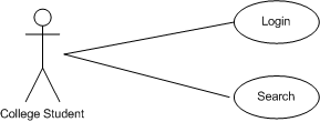
The use case below shows the student actor interacting with the application. A student can carry out two tasks with the application - login and search for books.

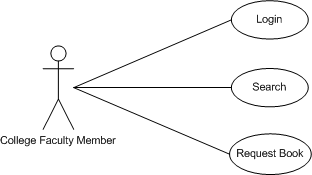
The use case below shows the college faculty actor interacting with the application. A faculty member can carry out three tasks with the application - login, request books and search for books.

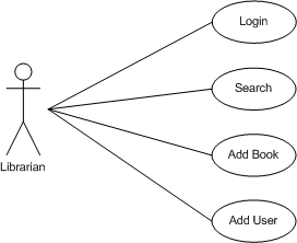
The use case below shows the librarian actor interacting with the application. A librarian can carry out four tasks with the application - login, search for books, add a book and add a user.

External Dependencies
External dependencies are items external to the code of the application that may pose a threat to the application. These items are typically still within the control of the organisation but possibly not within the control of the development team. The first area to look at when investigating external dependencies is how will the application be deployed in a production environment and what are the requirements surrounding this. This involves looking at how the application is or is not intended to be run. For example if the application is expected to be run on a server that has been hardened to the organisations hardening standard and it is expected to sit behind a firewall then this information should be documented in the external dependencies section. External dependencies should be documented as follows:
- ID - A unique ID assigned to the external dependency.
- Description - A textual description of the external dependency.
Example:
| External Dependencies | |
|---|---|
| ID | Description |
| 1 | The college library website will run on a Linux server running apache. This server will be hardened as per the colleges server hardening standard. This includes the application of the latest operating system and application security patches. |
| 2 | The database server will be mysql and it will run on a Linux server. This server will be hardened as per the colleges server hardening standard. This will include the application of the lastest operating system and application security patches. |
| 3 | The connection between the Web Server and the database server will be over a private network. |
Entry Points
Entry points define the interfaces through which potential attackers can interact with the application or supply it with data. In order for potential attacker to attack an application entry points must exist. Entry points in an application can be layered, for example each web page in a web application may contain multiple entry points. Entry points should be documented as follows:
- ID - A unique ID assigned to the entry point. This will be used to cross reference the entry point with any threats or vulnerabilities that are identified. In the case of layer entry points a major.minor notation should be used.
- Name - A descriptive name identifying the entry point and its purpose.
- Description - A textual description detailing the interaction or processing that occurs at the entry point.
- Trust Levels - The level of access required at the entry point is documented here. These will be cross referenced with the trusts levels defined later in the document.
Example:
Assets
The system must have something that the attacker is interested in, these items/areas of interest are defined as assets. Assets are essentially threat targets, i.e. they are the reason threats will exist. Assets can be both physical assets and abstract assets. For example an asset of an application might be a list of clients and their personal information, this is a physical asset. An abstract asset might be the reputation of an organsation. Assets are documented in the threat model as follows:
- ID - A unique ID is assigned to identify each asset. This will be used to cross reference the asset with any threats or vulnerabilities that are identified.
- Name - A descriptive name that clearly identifies the asset.
- Description - A textual description of what the asset is and why it needs to be protected.
- Trust Levels - The level of access required to access the entry point is documented here. These will be cross referenced with the trust levels defined in the next step.
Example:
Trust Levels
Trust levels represent the access rights that the application will grant to external entities. The trust levels are cross referenced with the entry points and assets. This allows us to defined the access rights or privileges required at each entry point and those required to interact with each asset. Trust levels are documented in the threat model as follows:
- ID - A unique number is assigned to each trust level. This is used to cross reference the trust level with the entry points and assets.
- Name - A descriptive name that allows you to identify the external entities that have been granted this trust level.
- Description - A textual description of the trust level detailing the external entity who has been granted the trust level.
Example:
Data Flow Diagrams
All of the information collected allows us to accurately model the application through the use of Data Flow Diagrams (DFDs). The DFDs will allow us to gain a better understanding of the application by providing a visual representation of how the application processes data. The focus of the DFDs is on how data moves through the application and what happens to the data as it moves. DFDs are hierarchical in structure so they can be used to decompose the application into subsystems and lower-level subsystems. The high level DFD will allow us to clarify the scope of the application being modeled. The lower level iterations will allow us to focus on the specific processes involved when processing specific data. There are a number of symbols that are used in DFDs for threat modeling. These are described below:
External Entity
The external entity shape is used to represent any entity outside the application that interacts with the application via an entry point.
![]()
Process
The process shape represents a task that handles data within the application. The task may process the data or perform an action based on the data.

Multiple Process
The multiple process shape is used to present a collection of subprocesses. The multiple process can be broken down into its subprocesses in another DFD.

Data Store
The data store shape is used to represent locations where data is stored. Data stores do not modify the data they only store data.
![]()
Data Flow
The data flow shape represents data movement within the application. The direction of the data movement is represented by the arrow.
![]()
Privilege Boundary
The privilege boundary shape is used to represent the change of privilege levels as the data flows through the application.
![]()
Example: